What is the voltage at a node between two series voltage sources? Here, the total number of independent nodal pair equations required is one less than the total number of junctions present in the network. How to encourage melee combat when ranged is a stronger option. 3. Like this: Let the voltages at nodes N1, N2 and N3 be called \$v_1\$, \$v_2\$ and \$v_3\$, respectively. 4. Table 1: Example node method KCL solutions for resistor bridge circuit. I looked more seriously and as @Andy aka just said: The linked question has nothing to do with this question. Mark all the node voltages with regard to the ground terminal from all principal nodes other than the reference node. Cover letter to article submitted by someone besides the corresponding author, Scientific writing: attributing actions to inanimate objects. How should we do boxplots with small samples? Do Schwarzschild black holes exist in reality? Thus no, Vo (I suspect that Vo is the thing that would be zero) is not equal to zero here. So far, we have always referred to voltage as a drop across an element. nodal analysis voltage dependent source problems solved nodes liwvuP/J_B6C5`.2
ymXUYpOz 7^^Ou"6{2mZID7fy"1xvY)&Nv If this doesn't address your question, then follow-up in the comments or with an edit to your question.
12 0 obj
<<
/Length 13 0 R
/Filter /FlateDecode
>>
stream
The equations for the voltages at nodes 2 and 3 are self-evident. *:JZjz ? Use MathJax to format equations. 6: Supernode encapsulating floating voltage source. 464), How APIs can take the pain out of legacy system headaches (Ep. How to clamp an e-bike on a repair stand? The KCL equations at those two nodes are obtained by equating total currents flowing in with total currents flowing out. WI$I$_I$I$_I$IsVS u [}O 1 m? P_I$I$_ : g\?]I%I$Ir[?W#Od *{'\UH ?bI$I$_I$I$_I$I$_= ^HC:c @ t+I$I$I$_I$I$_I%u [}O 1 m? P\_ / At]:I$I$_?g] w]I$I/I%}l _= Z.Sgr[?W#Od ]ZI$I$_I$I$_I$I$_HC: :*0 u uTa BI$I$I$_I$I$_1 m? P\_ / AsVS t$I$Ip 3 u I$I$_)UR?OkXO 'Z}l _= Z.ukI$I$I$_I$I$_I$Is :*0 u ?Q C\?$ J?zI$I$_I$I$_I$I$_ +o _ B +o _ B +o _ BNtI$_I% :pI$I+/E54,pkZrN+/E54,pkZrN+/E54,pkZrNzlew~65W[M`;}lOV_}7c]eu Jzlew~65W[M`;d=vXaNc~t]yeF,mn0 QY:]#6{I$I$I$_I$I$_>:_Gv_R
84I'^>#]Xt4lOae
{ .B]YYd3qfSo6}" p3B]YYd3qfSo6}" p3B]YYd3qfSo6}" p3u>1^^=F\OuLFedg4wSSx5l?0I$I$_I$I$_I$Iro>{C3_mM2uo]~M}4k\W!
w435.ApOi_I$I$_ : g\?F 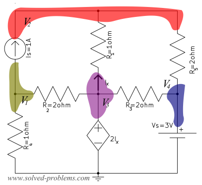 \begin{align}
  Can a human colony be self-sustaining without sunlight using mushrooms? EDIT: I am not removing the linked question and redoing the question. $$ You can sum the currents out of the supernode: Given resistor values $R_1$ to $R_5$, we can solve these two equations for the two unknown node voltages $V_a$ and $V_b$, from which we can determine any voltage drop or current in the circuit. It only takes a minute to sign up. In the US, how do we make tax withholding less if we lost our job for a few months? Thanks for contributing an answer to Electrical Engineering Stack Exchange! Across a supernode, your variables should include the value of the enclosed floating voltage source. Determine the unknown node voltages by simultaneously solving the KCL equations. By clicking Post Your Answer, you agree to our terms of service, privacy policy and cookie policy. %PDF-1.2
%
_3o(OY0w6I3'Qio{>hku>
/ProcSet 2 0 R
>>
/Contents 12 0 R
>>
endobj
17 0 obj
<<
/Length 18 0 R
/Filter /FlateDecode
>>
stream
Making statements based on opinion; back them up with references or personal experience. \begin{align} The nodal equations are written using Kirchhoffs current and. At a particular node, the sum of currents entering into the node should be similar in value to the sum of currents leaving at that node. Use the node voltages to obtain desired quantities in the circuit. Find the node voltages at each node and the node voltages can be obtained by solving the equations that are obtained in the above step. Since all the currents flow through resistors, we can rewrite these equations in terms of the node voltages by using equations $\eqref{NDM-ER5}$ to $\eqref{NDM-ER4}$. For all the principal nodes, write the nodal equations except for the reference node. But if there are two or more voltage sources not all connected to a common node, then at least one of them cannot be connected to the ground. Use the node method to analyze circuits when you cannot use any other shortcuts. A resistor bridge circuit has no pair of resistors in series or parallel. &HGz@3b|)O&|.Gs=P37vQN(C.r#-1nn*GM*0F5wK(\lZh Tv-Wml`B`G}p^*E:#EI^(MT77{'xWBP]!\+N3}g^?WCg
9Q=u5z=:y%wG+
I^L&Ok.]`?dBlBAA,f]}\R
endstream
endobj
18 0 obj
469
endobj
19 0 obj
<<
/Type /XObject
/Subtype /Image
/Name /im1
/Filter /DCTDecode
/Width 306
/Height 148
/BitsPerComponent 8
/ColorSpace /DeviceRGB
/Length 20 0 R
>>
stream
In this way, both nodes connected to the voltage source have node voltages that are known.
Can a human colony be self-sustaining without sunlight using mushrooms? EDIT: I am not removing the linked question and redoing the question. $$ You can sum the currents out of the supernode: Given resistor values $R_1$ to $R_5$, we can solve these two equations for the two unknown node voltages $V_a$ and $V_b$, from which we can determine any voltage drop or current in the circuit. It only takes a minute to sign up. In the US, how do we make tax withholding less if we lost our job for a few months? Thanks for contributing an answer to Electrical Engineering Stack Exchange! Across a supernode, your variables should include the value of the enclosed floating voltage source. Determine the unknown node voltages by simultaneously solving the KCL equations. By clicking Post Your Answer, you agree to our terms of service, privacy policy and cookie policy. %PDF-1.2
%
_3o(OY0w6I3'Qio{>hku>
/ProcSet 2 0 R
>>
/Contents 12 0 R
>>
endobj
17 0 obj
<<
/Length 18 0 R
/Filter /FlateDecode
>>
stream
Making statements based on opinion; back them up with references or personal experience. \begin{align} The nodal equations are written using Kirchhoffs current and. At a particular node, the sum of currents entering into the node should be similar in value to the sum of currents leaving at that node. Use the node voltages to obtain desired quantities in the circuit. Find the node voltages at each node and the node voltages can be obtained by solving the equations that are obtained in the above step. Since all the currents flow through resistors, we can rewrite these equations in terms of the node voltages by using equations $\eqref{NDM-ER5}$ to $\eqref{NDM-ER4}$. For all the principal nodes, write the nodal equations except for the reference node. But if there are two or more voltage sources not all connected to a common node, then at least one of them cannot be connected to the ground. Use the node method to analyze circuits when you cannot use any other shortcuts. A resistor bridge circuit has no pair of resistors in series or parallel. &HGz@3b|)O&|.Gs=P37vQN(C.r#-1nn*GM*0F5wK(\lZh Tv-Wml`B`G}p^*E:#EI^(MT77{'xWBP]!\+N3}g^?WCg
9Q=u5z=:y%wG+
I^L&Ok.]`?dBlBAA,f]}\R
endstream
endobj
18 0 obj
469
endobj
19 0 obj
<<
/Type /XObject
/Subtype /Image
/Name /im1
/Filter /DCTDecode
/Width 306
/Height 148
/BitsPerComponent 8
/ColorSpace /DeviceRGB
/Length 20 0 R
>>
stream
In this way, both nodes connected to the voltage source have node voltages that are known. 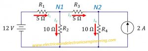 To learn more, see our tips on writing great answers. How do you formulate the equation at that certain node with those branches connected? analysis nodal step circuits electrical4u electric solve equations values iv example Circuit Analysis Problem, KCL Nodal Analysis with Supernode, Nodal analysis in circuit contain voltage controlled voltage source, Blondie's Heart of Glass shimmering cascade effect. MathJax reference. voltage sources branch circuit multiple thanks Announcing the Stacks Editor Beta release!
 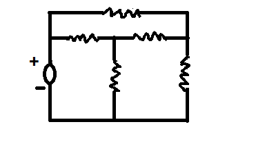 The circuit analysis can be done with n-1independent nodal equations when there n nodes in the circuit. If there are any floating voltages (ones connected to unknown node voltages), enclose each of them in a supernode. Mo1i&C8Z6lU\lx,sI2fBg[mqcI`^~6Zjt~&^~6Zjt~&^~6Zjt~&L6V[PThd9yle90S7~sayQ $sZ Ig9is $z/L ]3Y\],Ux Dkz/L ]3Y\],Ux Dkz/L ]3Y\],Ux DkzUVFSx C1pVzUVFSx C1pVzUVFSx C1pV/Uec. This feature allows a motor (for example) connected across the bridge to be spun either clockwise or counterclockwise. It's difficult to ascertain precisely what your question is so this is just a stab at an answer.
 How do you formulate an equation on a node with two voltage sources connected in it, regardless if it is a supernode or not? An additional question as well. \frac{15-V_a}{R_1} &= \frac{V_a-0}{R_3}+\frac{V_a-V_b}{R_5} \label{NDM-KCA}\\ $$ There are two unknown node voltages $V_a$ and $V_b$ in Fig. Is "Occupation Japan" idiomatic? +k `x#HX{ |,.\)t#dH,1)DyJmI XY v]R[lc|1P}qzSHpD8.${"^=-A
>ob#*
1&tf(-1WZ\Y7Z'GP%^U7:Sd$J-3%.hdsgHLujM*{ N N.`Rh6:f \:i`F'c[y8*i"dct!hEj'KFN)/qZAXJ!' A> I2AjAI>~0`0 (
jlANK4xEd3$,.1E{yuH\fmY.wi Fig. The non-reference nodes in the circuit have constant voltage values and the reference node stands as a reference for all the other remaining nodes in the circuit. You take nodes 1, 2 and 3 together as a single node, called a generalized node, aka supernode, for current summing purposes, and create an equation for that. Consider the circuit below. In the linked question above, both voltage sources have the same value for voltage. 2022 Community Moderator Election Results. HUN0Rv|YE/~@Rn/*q-(/N
+ Y!rq&GE{ s&pa9FkBv 3d(4[5$ZSI-= ^`vVY<68^~3SyuaK;,'zLo{q(a>YxV>JmWpIilGTU^tW Supernodes are not pre-defined as part of the circuit. Nodal analysis is a powerful mechanism, and it works depending on the similar concept of matrix analysis. Now, we define a zero voltage level called ground, so that every node in a circuit can have a node voltage relative to that ground.
! I_2+I_5 &= I_4 Usually, if there is only one voltage source connected to the node, and if it is connected to the ground, you just equate V to the value of voltage source. This analysis is operated either in frequency or time domains but constrained for time-invariant systems. HVr8=zSB V]MsNSu eEH T_! I think you are confused with nodal analysis concepts (in particular with supernodes and references). (3P0t} nodal supernode If not, how should you create the nodal equation for node 1? The following table gives examples of calculating $V_a$ and $V_b$ (from equations $\eqref{NDM-KCA}$ and $\eqref{NDM-KCB}$) as well as the bridge current $I_5$ (from equation $\eqref{NDM-ER5}$) given known values of $R_1$ to $R_5$. Table 2: Example node method KCL solutions for voltage source bridge circuit. We call these these ones floating voltage sources because their adjacent node voltages are unknown. Nodal analysis is generally applicable for the networks that have multiple parallel circuits with a common ground terminal. How should I deal with coworkers not respecting my blocking off time in my calendar for work? 7: Flowchart for node method circuit analysis. Connect and share knowledge within a single location that is structured and easy to search. In general, you don't create an equation for node 1. Determining the voltage labeled Vx by Nodal Analysis [Voltage Controlled Current Source], Setting ground potential in nodal analysis matrix form.
a !1AQa"q2B#$Rb34rC%Scs5&DTdEt6UeuF'Vfv7GWgw(8HXhx )9IYiy Label all unknown node voltages using variables. WatElectrical.com | Contact Us | Privacy Policy, Please refer to this link to know more about, What is Linear Induction Motor : Working, Construction, & Its Applications, What is a Power Triangle : Formula and Its Working, What is a 7805 Voltage Regulator : Working & Its Applications, What is Moving Coil Galvanometer : Working & Its Applications, Step Down Transformer : Working & Its Applications, What is Tesla Turbine : Design & Its Efficiency, What is Tesla Coil : Working Principle & Its Applications, What is Surge Arrester : Working, Types & Its Applications, What is a Form Factor : Peak Factor & Its Derivations, What is Nodal Analysis : Features & Its Examples, Here, at specific nodes, the voltage values are observed, Here, at specific nodes, the current values are observed, Using Ohms law, KCL equations are represented in the form of node voltages, Using Ohms law, KVL equations are represented in the form of mesh currents. mesh They are something you define when doing the nodal analysis. After you have defined supernodes that encompass all the voltage sources in your circuit, all of the voltage sources will be "hidden" within supernodes and there will be no need to write equations for nodes with voltage sources connected to them. analysis nodal node electric circuits electrical4u nodes current ohm law example To subscribe to this RSS feed, copy and paste this URL into your RSS reader. The standard of elder sister in mainland China. (instead of occupation of Japan, occupied Japan or Occupation-era Japan), Incremented index on a splited polyline in QGIS, Formal proof that two Eigenvalues have to be equal. "(($#$% '+++,.3332-3333333333 2 So, using node voltages the current and voltage values can be calculated for each element in the circuit. Bridge topologies are common structures in circuits because they usually permit current to flow in either direction across the "bridge". Fig. Write and solve KCL equations at all nodes with unknown node voltages. Use these voltage sources to label known node voltages. When you find a voltage source in your circuit, it is up to you to define a new supernode that encompasses the two nodes connected to the source. The total number of nodal equations and the total number of non-reference nodes in the circuit to be obtained are the same. \frac{15-V_b}{R_2}+\frac{V_a-V_b}{R_5} &= \frac{V_b-0}{R_4} \label{NDM-KCB} "^#:C Every resistor's voltage drop and current can be expressed in terms of node voltages. The flowchart shown below efficiently solves a circuit with sources and resistors using the node method. Draw a circuit diagram with the current values specified at every node, Choose a reference node (which is generally ground terminal) and at every node write the variable for voltage corresponding to the reference node, Use the KCL principle at each node and write equations w.r.t circuit impedance and voltages at adjacent nodes, As per the obtained equations in the above step, rewrite those in matrix form and solve the matrix equation through the inverse matrix technique, A supernode does not possess voltage by itself, In solving the supernode, either KVL or KCL principle can be applied, Any component can be in parallel connection with voltage source so that a supernode is formed, The functionality of Kirchhoffs current law for supernode is the same as a general node. (You may ignore the statements below this.). \end{align} How do I replace a toilet supply stop valve attached to copper pipe? The circuit below has 30 V and 20 V. Will it still be zero just like the one in the linked question? What do you want to compute ? It's not the same topology. You now have three unknowns and one equation, but you know that \$ v_2 = v_1 - 30 \$ and \$v3 = v1 - 20\$, so you can back-substitute into the previous equation and solve it for \$v_1\$. rev2022.7.20.42634. Adobe d C
The linked question has nothing to do with this question other than it concerns voltages at nodes, but which nodes I wonder? circuits resistor Find all the principal nodes present in the circuit and choose one as a reference node and this reference node acts as a ground terminal. 465). \frac{v_2}{ 2\mathrm{k\Omega}} + \frac{v_3}{ 5\mathrm{k\Omega} }+\frac{v_1}{ 4\mathrm{k\Omega} }= 0 Dependant sources are handled in the same manner. The best answers are voted up and rise to the top, Start here for a quick overview of the site, Detailed answers to any questions you might have, Discuss the workings and policies of this site, Learn more about Stack Overflow the company. What if there are two voltage sources, but the other one is not independent but a VCVS or CCVS? Across a supernode, your variables should include the value of the enclosed floating voltage source, University of Illinois at Urbana-Champaign, Department of Electrical and Computer Engineering, $\begin{aligned} R_1&=R_2=R_3=R_5=5\text{ k}\Omega \\ R_4&=1\text{ k}\Omega \end{aligned}$, $\begin{aligned} V_a&=6\text{ V} \\ V_b&=3\text{ V} \end{aligned}$, $\begin{aligned} I_5 &=0.6\text{ mA} \end{aligned}$, $\begin{aligned} R_1&=R_2=R_3=R_5=5\text{ k}\Omega \\ R_4&=5\text{ k}\Omega \end{aligned}$, $\begin{aligned} V_a&=7.5\text{ V} \\ V_b&=7.5\text{ V} \end{aligned}$, $\begin{aligned} I_5 &=0\text{ mA} \end{aligned}$, $\begin{aligned} R_1&=R_2=R_3=R_5=5\text{ k}\Omega \\ R_4&=9\text{ k}\Omega \end{aligned}$, $\begin{aligned} V_a&=8\text{ V} \\ V_b&=9\text{ V} \end{aligned}$, $\begin{aligned} I_5 &=-0.2\text{ mA} \end{aligned}$, $\begin{aligned} R_1&=R_2=R_3=5\text{ k}\Omega \\ R_4&=1\text{ k}\Omega \end{aligned}$, $\begin{aligned} V_a&=0\text{ V} \\ V_a+5&=5\text{ V} \end{aligned}$, $\begin{aligned} I_1 &=3\text{ mA} \\ I_3 &=0\text{ mA} \end{aligned}$, $\begin{aligned} I_x &=3\text{ mA} \end{aligned}$, $\begin{aligned} R_1&=R_2=R_3=5\text{ k}\Omega \\ R_4&=5\text{ k}\Omega \end{aligned}$, $\begin{aligned} V_a&=5\text{ V} \\ V_a+5&=10\text{ V} \end{aligned}$, $\begin{aligned} I_1 &=2\text{ mA} \\ I_3 &=1\text{ mA} \end{aligned}$, $\begin{aligned} I_x &=1\text{ mA} \end{aligned}$, $\begin{aligned} R_1&=R_2=R_3=5\text{ k}\Omega \\ R_4&=9\text{ k}\Omega \end{aligned}$, $\begin{aligned} V_a&=6.25\text{ V} \\ V_a+5&=11.25\text{ V} \end{aligned}$, $\begin{aligned} I_1 &=1.75\text{ mA} \\ I_3 &=1.25\text{ mA} \end{aligned}$, $\begin{aligned} I_x &=0.5\text{ mA} \end{aligned}$. Site design / logo 2022 Stack Exchange Inc; user contributions licensed under CC BY-SA. I_1 &= I_3+I_5\\ Enclose floating voltage sources in supernodes. Attach a ground to the node connected to as many voltage sources as possible. Look at the Voltage sources, they are reversed in the question you linked to, and not in this schematics. Why does KLM offer this specific combination of flights (GRU -> AMS -> POZ) just on one day when there's a time change? How to find the nodal voltage when there is a voltage source across two nodes? Just by staring at the schematics. Though this question has been answered here, I still have doubts in mind. If a creature with damage transfer is grappling a target, and the grappled target hits the creature, does the target still take half the damage?
How do you formulate an equation on a node with two voltage sources connected in it, regardless if it is a supernode or not? An additional question as well. \frac{15-V_a}{R_1} &= \frac{V_a-0}{R_3}+\frac{V_a-V_b}{R_5} \label{NDM-KCA}\\ $$ There are two unknown node voltages $V_a$ and $V_b$ in Fig. Is "Occupation Japan" idiomatic? +k `x#HX{ |,.\)t#dH,1)DyJmI XY v]R[lc|1P}qzSHpD8.${"^=-A
>ob#*
1&tf(-1WZ\Y7Z'GP%^U7:Sd$J-3%.hdsgHLujM*{ N N.`Rh6:f \:i`F'c[y8*i"dct!hEj'KFN)/qZAXJ!' A> I2AjAI>~0`0 (
jlANK4xEd3$,.1E{yuH\fmY.wi Fig. The non-reference nodes in the circuit have constant voltage values and the reference node stands as a reference for all the other remaining nodes in the circuit. You take nodes 1, 2 and 3 together as a single node, called a generalized node, aka supernode, for current summing purposes, and create an equation for that. Consider the circuit below. In the linked question above, both voltage sources have the same value for voltage. 2022 Community Moderator Election Results. HUN0Rv|YE/~@Rn/*q-(/N
+ Y!rq&GE{ s&pa9FkBv 3d(4[5$ZSI-= ^`vVY<68^~3SyuaK;,'zLo{q(a>YxV>JmWpIilGTU^tW Supernodes are not pre-defined as part of the circuit. Nodal analysis is a powerful mechanism, and it works depending on the similar concept of matrix analysis. Now, we define a zero voltage level called ground, so that every node in a circuit can have a node voltage relative to that ground.
! I_2+I_5 &= I_4 Usually, if there is only one voltage source connected to the node, and if it is connected to the ground, you just equate V to the value of voltage source. This analysis is operated either in frequency or time domains but constrained for time-invariant systems. HVr8=zSB V]MsNSu eEH T_! I think you are confused with nodal analysis concepts (in particular with supernodes and references). (3P0t} nodal supernode If not, how should you create the nodal equation for node 1? The following table gives examples of calculating $V_a$ and $V_b$ (from equations $\eqref{NDM-KCA}$ and $\eqref{NDM-KCB}$) as well as the bridge current $I_5$ (from equation $\eqref{NDM-ER5}$) given known values of $R_1$ to $R_5$. Table 2: Example node method KCL solutions for voltage source bridge circuit. We call these these ones floating voltage sources because their adjacent node voltages are unknown. Nodal analysis is generally applicable for the networks that have multiple parallel circuits with a common ground terminal. How should I deal with coworkers not respecting my blocking off time in my calendar for work? 7: Flowchart for node method circuit analysis. Connect and share knowledge within a single location that is structured and easy to search. In general, you don't create an equation for node 1. Determining the voltage labeled Vx by Nodal Analysis [Voltage Controlled Current Source], Setting ground potential in nodal analysis matrix form.
a !1AQa"q2B#$Rb34rC%Scs5&DTdEt6UeuF'Vfv7GWgw(8HXhx )9IYiy Label all unknown node voltages using variables. WatElectrical.com | Contact Us | Privacy Policy, Please refer to this link to know more about, What is Linear Induction Motor : Working, Construction, & Its Applications, What is a Power Triangle : Formula and Its Working, What is a 7805 Voltage Regulator : Working & Its Applications, What is Moving Coil Galvanometer : Working & Its Applications, Step Down Transformer : Working & Its Applications, What is Tesla Turbine : Design & Its Efficiency, What is Tesla Coil : Working Principle & Its Applications, What is Surge Arrester : Working, Types & Its Applications, What is a Form Factor : Peak Factor & Its Derivations, What is Nodal Analysis : Features & Its Examples, Here, at specific nodes, the voltage values are observed, Here, at specific nodes, the current values are observed, Using Ohms law, KCL equations are represented in the form of node voltages, Using Ohms law, KVL equations are represented in the form of mesh currents. mesh They are something you define when doing the nodal analysis. After you have defined supernodes that encompass all the voltage sources in your circuit, all of the voltage sources will be "hidden" within supernodes and there will be no need to write equations for nodes with voltage sources connected to them. analysis nodal node electric circuits electrical4u nodes current ohm law example To subscribe to this RSS feed, copy and paste this URL into your RSS reader. The standard of elder sister in mainland China. (instead of occupation of Japan, occupied Japan or Occupation-era Japan), Incremented index on a splited polyline in QGIS, Formal proof that two Eigenvalues have to be equal. "(($#$% '+++,.3332-3333333333 2 So, using node voltages the current and voltage values can be calculated for each element in the circuit. Bridge topologies are common structures in circuits because they usually permit current to flow in either direction across the "bridge". Fig. Write and solve KCL equations at all nodes with unknown node voltages. Use these voltage sources to label known node voltages. When you find a voltage source in your circuit, it is up to you to define a new supernode that encompasses the two nodes connected to the source. The total number of nodal equations and the total number of non-reference nodes in the circuit to be obtained are the same. \frac{15-V_b}{R_2}+\frac{V_a-V_b}{R_5} &= \frac{V_b-0}{R_4} \label{NDM-KCB} "^#:C Every resistor's voltage drop and current can be expressed in terms of node voltages. The flowchart shown below efficiently solves a circuit with sources and resistors using the node method. Draw a circuit diagram with the current values specified at every node, Choose a reference node (which is generally ground terminal) and at every node write the variable for voltage corresponding to the reference node, Use the KCL principle at each node and write equations w.r.t circuit impedance and voltages at adjacent nodes, As per the obtained equations in the above step, rewrite those in matrix form and solve the matrix equation through the inverse matrix technique, A supernode does not possess voltage by itself, In solving the supernode, either KVL or KCL principle can be applied, Any component can be in parallel connection with voltage source so that a supernode is formed, The functionality of Kirchhoffs current law for supernode is the same as a general node. (You may ignore the statements below this.). \end{align} How do I replace a toilet supply stop valve attached to copper pipe? The circuit below has 30 V and 20 V. Will it still be zero just like the one in the linked question? What do you want to compute ? It's not the same topology. You now have three unknowns and one equation, but you know that \$ v_2 = v_1 - 30 \$ and \$v3 = v1 - 20\$, so you can back-substitute into the previous equation and solve it for \$v_1\$. rev2022.7.20.42634. Adobe d C
The linked question has nothing to do with this question other than it concerns voltages at nodes, but which nodes I wonder? circuits resistor Find all the principal nodes present in the circuit and choose one as a reference node and this reference node acts as a ground terminal. 465). \frac{v_2}{ 2\mathrm{k\Omega}} + \frac{v_3}{ 5\mathrm{k\Omega} }+\frac{v_1}{ 4\mathrm{k\Omega} }= 0 Dependant sources are handled in the same manner. The best answers are voted up and rise to the top, Start here for a quick overview of the site, Detailed answers to any questions you might have, Discuss the workings and policies of this site, Learn more about Stack Overflow the company. What if there are two voltage sources, but the other one is not independent but a VCVS or CCVS? Across a supernode, your variables should include the value of the enclosed floating voltage source, University of Illinois at Urbana-Champaign, Department of Electrical and Computer Engineering, $\begin{aligned} R_1&=R_2=R_3=R_5=5\text{ k}\Omega \\ R_4&=1\text{ k}\Omega \end{aligned}$, $\begin{aligned} V_a&=6\text{ V} \\ V_b&=3\text{ V} \end{aligned}$, $\begin{aligned} I_5 &=0.6\text{ mA} \end{aligned}$, $\begin{aligned} R_1&=R_2=R_3=R_5=5\text{ k}\Omega \\ R_4&=5\text{ k}\Omega \end{aligned}$, $\begin{aligned} V_a&=7.5\text{ V} \\ V_b&=7.5\text{ V} \end{aligned}$, $\begin{aligned} I_5 &=0\text{ mA} \end{aligned}$, $\begin{aligned} R_1&=R_2=R_3=R_5=5\text{ k}\Omega \\ R_4&=9\text{ k}\Omega \end{aligned}$, $\begin{aligned} V_a&=8\text{ V} \\ V_b&=9\text{ V} \end{aligned}$, $\begin{aligned} I_5 &=-0.2\text{ mA} \end{aligned}$, $\begin{aligned} R_1&=R_2=R_3=5\text{ k}\Omega \\ R_4&=1\text{ k}\Omega \end{aligned}$, $\begin{aligned} V_a&=0\text{ V} \\ V_a+5&=5\text{ V} \end{aligned}$, $\begin{aligned} I_1 &=3\text{ mA} \\ I_3 &=0\text{ mA} \end{aligned}$, $\begin{aligned} I_x &=3\text{ mA} \end{aligned}$, $\begin{aligned} R_1&=R_2=R_3=5\text{ k}\Omega \\ R_4&=5\text{ k}\Omega \end{aligned}$, $\begin{aligned} V_a&=5\text{ V} \\ V_a+5&=10\text{ V} \end{aligned}$, $\begin{aligned} I_1 &=2\text{ mA} \\ I_3 &=1\text{ mA} \end{aligned}$, $\begin{aligned} I_x &=1\text{ mA} \end{aligned}$, $\begin{aligned} R_1&=R_2=R_3=5\text{ k}\Omega \\ R_4&=9\text{ k}\Omega \end{aligned}$, $\begin{aligned} V_a&=6.25\text{ V} \\ V_a+5&=11.25\text{ V} \end{aligned}$, $\begin{aligned} I_1 &=1.75\text{ mA} \\ I_3 &=1.25\text{ mA} \end{aligned}$, $\begin{aligned} I_x &=0.5\text{ mA} \end{aligned}$. Site design / logo 2022 Stack Exchange Inc; user contributions licensed under CC BY-SA. I_1 &= I_3+I_5\\ Enclose floating voltage sources in supernodes. Attach a ground to the node connected to as many voltage sources as possible. Look at the Voltage sources, they are reversed in the question you linked to, and not in this schematics. Why does KLM offer this specific combination of flights (GRU -> AMS -> POZ) just on one day when there's a time change? How to find the nodal voltage when there is a voltage source across two nodes? Just by staring at the schematics. Though this question has been answered here, I still have doubts in mind. If a creature with damage transfer is grappling a target, and the grappled target hits the creature, does the target still take half the damage?  Laymen's description of "modals" to clients. When there is just one voltage source in a circuit, you should attach the ground to one of the nodes connected to that voltage source, just as in Fig. By clicking Accept all cookies, you agree Stack Exchange can store cookies on your device and disclose information in accordance with our Cookie Policy. nodal kirchhoff Stack Exchange network consists of 180 Q&A communities including Stack Overflow, the largest, most trusted online community for developers to learn, share their knowledge, and build their careers. (Let's say below, if there is no 2 k resistor below node 2, V1 = 30 V.). \end{align} What's inside the SPIKE Essential small angular motor? If, say, the 30V source were a controlled source, e.g, \$(k \cdot v_O)\$, the first term in the above equation becomes: $$\dfrac{v_O - k\cdot v_O}{2k\Omega} = \dfrac{v_O(1-k)}{2k\Omega}$$.
  $$\dfrac{v_O - 30V}{2k\Omega} + \dfrac{v_O - 20V}{5k \Omega} + \dfrac{v_O}{4k\Omega} = 0 $$. Electrical Engineering Stack Exchange is a question and answer site for electronics and electrical engineering professionals, students, and enthusiasts. Use this technique when you cannot simplify the circuit any further using circuit analysis shortcuts. I suggest you check these concepts again :), Code completion isnt magic; it just feels that way (Ep. The circuit you linked is not related with this one. Write a KCL equation at every supernode and at every other unknown node in terms of node voltages. I$I$_u yuVx8CM_vn@}F=O}{n]B{r1"~`-o> >7G[? * OzRT 8 - o> >7 8N OzRT 8 - /o> >7y'q?K[? *_}I |oOR OzRUo> >7 8N OzRT 8 - /o> >7y'q?K[? *_}I |oOR OzRUo> >7 8N OzRT 8 - /o> >7y'q?K[? *?3;
;Cmy!|%?QhgLn
)Lu=.C:f-[p'Hh%o> >7 8N OzRT 8 - /o> >7y'q?K[? *_}I |oOR OzRUo> >7 8N OzRT 8 - /o> >7y'q?K[? *_}I |oOR OzRUo> >7 8N OzRT 8 - /o> >7y'q?K[? *_}I |oOR OzRU>t>fx,n|x^!g=1D#C^>anLF*+]RI$II% :pI$I$__ 'Z[?W#Od ~G kVI$I$I$_I$I$_I%c @ { P Fs :*0 u] Asking for help, clarification, or responding to other answers.
$$\dfrac{v_O - 30V}{2k\Omega} + \dfrac{v_O - 20V}{5k \Omega} + \dfrac{v_O}{4k\Omega} = 0 $$. Electrical Engineering Stack Exchange is a question and answer site for electronics and electrical engineering professionals, students, and enthusiasts. Use this technique when you cannot simplify the circuit any further using circuit analysis shortcuts. I suggest you check these concepts again :), Code completion isnt magic; it just feels that way (Ep. The circuit you linked is not related with this one. Write a KCL equation at every supernode and at every other unknown node in terms of node voltages. I$I$_u yuVx8CM_vn@}F=O}{n]B{r1"~`-o> >7G[? * OzRT 8 - o> >7 8N OzRT 8 - /o> >7y'q?K[? *_}I |oOR OzRUo> >7 8N OzRT 8 - /o> >7y'q?K[? *_}I |oOR OzRUo> >7 8N OzRT 8 - /o> >7y'q?K[? *?3;
;Cmy!|%?QhgLn
)Lu=.C:f-[p'Hh%o> >7 8N OzRT 8 - /o> >7y'q?K[? *_}I |oOR OzRUo> >7 8N OzRT 8 - /o> >7y'q?K[? *_}I |oOR OzRUo> >7 8N OzRT 8 - /o> >7y'q?K[? *_}I |oOR OzRU>t>fx,n|x^!g=1D#C^>anLF*+]RI$II% :pI$I$__ 'Z[?W#Od ~G kVI$I$I$_I$I$_I%c @ { P Fs :*0 u] Asking for help, clarification, or responding to other answers.


best cities for indie musicians
Benleg- Delivering the dream